Project Overview

The purpose of the circuit designed in this project was to display my date of birth using a seven-segment display. Constraints were to use one NAND gate, one NOR gate, and common cathode display. My birthday is September 13, 2001, so my display will read 091301.
Truth Table

The purpose of a truth table is to see all the possible inputs and outputs in a logic expression. Here, the inputs are the X, Y, and Z switches. Turning each switch on/off will give you a different number on the seven segment display. The A-G columns are the different segments on the display. Each illuminates a different part of the display. The X's on the truth table are the don't-care conditions, meaning it doesn't matter if you get a 1 or a 0.
Karnaugh Maps/Simplified Logic
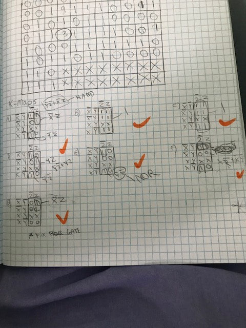
To K-map, you take the outputs from a truth table organize them into a table. Then, you group them wherever the output is one. The goal is to make the biggest groups possible, but you can only do it in multiples of 2. The expressions you get from the K-map are in sums of products form. When you make a group of 1's in the K-map, you must look at the variables that stay the same in each row and column. K-mapping is used instead of Boolean algebra here because it is faster and easier. There are so many expressions because there is a K-map for each of the 7 segments.
MultiSim Implementation
This is the Date of Birth circuit that I created on MultiSim. We were required to make one segment using NAND gates, and one using NOR gates.
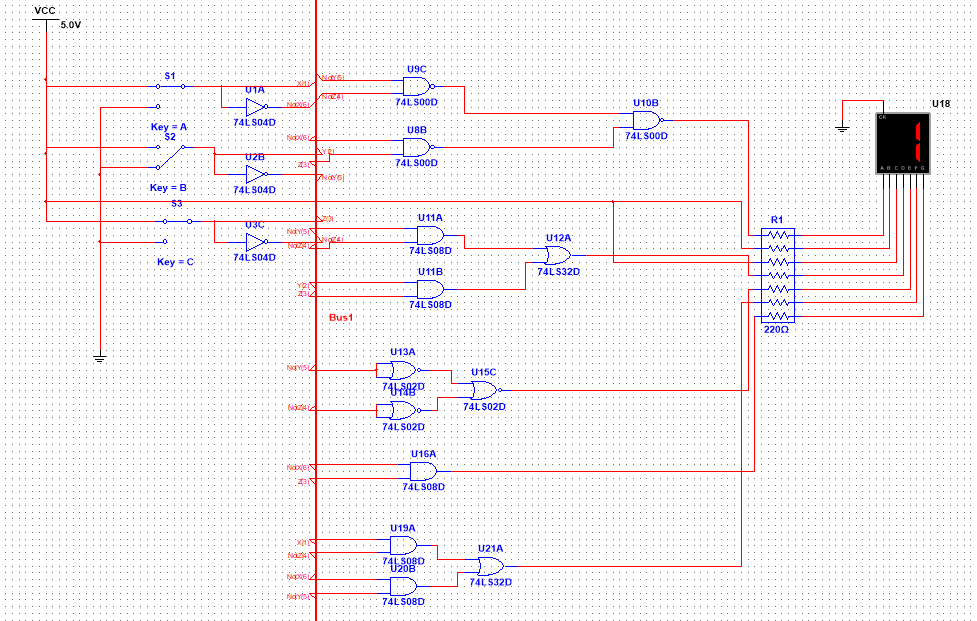
My circuit is in bus form. To create the circuit, you need 3 Inverters, 3 NAND gates, 3 NOR gates, 5 AND gates, and 2 OR gates. This means that you would need 5 chips. I chose to use NAND/NOR gates on circuits that could easily be simplified. NAND/NOR gates are used to simplify circuits and make them easier to build. My NAND and NOR gates didn't simplify anything, so it didn't matter that I used them. It didn't contain any fewer chips. A seven segment display has each one of 7 different segments light up a different part of a screen to display a message. Seven segment displays can be either common cathode or common anode. In common cathode, the display is wired to the ground. In common anode, the display is wired to the power. We used common cathode in this project, because the boards are already set up to it. The resistor before the seven segment display limits the current.
Bill of Materials
This table shows the different items we used and the amount to create the table.
Date of Birth Circuit Bill of Materials
Component |
Quantity |
Wires |
25+ |
Digital Logic Board |
1 |
74LS04 (Inverter) |
1 |
74LS32 (AND) |
1 |
74LS08 (OR) |
2 |
74LS00 (NAND) |
1 |
74LS02 (NOR) |
1 |
Bread-boarding

Circuit midway through
|

Top view of completed circuit
|

Side view of completed circuit
|
Overall, my second bread-boarding experience went well. I understood how to wire the board basically the whole way through, except for when I made one careless mistake that ruined the whole display. Ms. Zienty had to help me find the mistakes through the crowded breadboard. I messed up while connecting an AND gate to an OR gate. For the next time I breadboard, I now know to focus on not making any mistakes, because one small mistake can ruin the whole circuit.
Conclusion
This project taught me to be a little bit more careful about where I place every component of a breadboard. This is because one small mistake will ruin the whole circuit. It would've helped a bit if I was organized, and had my wires color coded. Also, if I were to create this circuit again, I would strategically place the chips that were used the most so that I wouldn't have to use extremely long wires everywhere, and my breadboard would be more organized. K-mapping is useful because sometimes the Boolean algebra is really long and repetitive to complete, like in the Majority Vote project. K-mapping is quicker and easier.
